FOUNDATION REPAIR
Underpinning with Helical Piles and Brackets: Load Transfer and Execution
How helical underpinning connects existing foundations to deeper support: brackets, load transfer, installation, preload, monitoring and project records.
What underpinning is intended to achieve
Underpinning introduces or improves support beneath an existing structure. A helical underpinning arrangement can connect an existing footing to a pile extending into suitable ground. The intended outcome may be stabilization, load redistribution or a specified movement correction. Those objectives are different and should be defined before installation.
Cracks, uneven floors or visible movement call for assessment; they do not on their own establish the cause or prove that a particular pile repair is appropriate. Review the structure, existing foundation, ground conditions and contributing issues such as drainage before defining the repair.
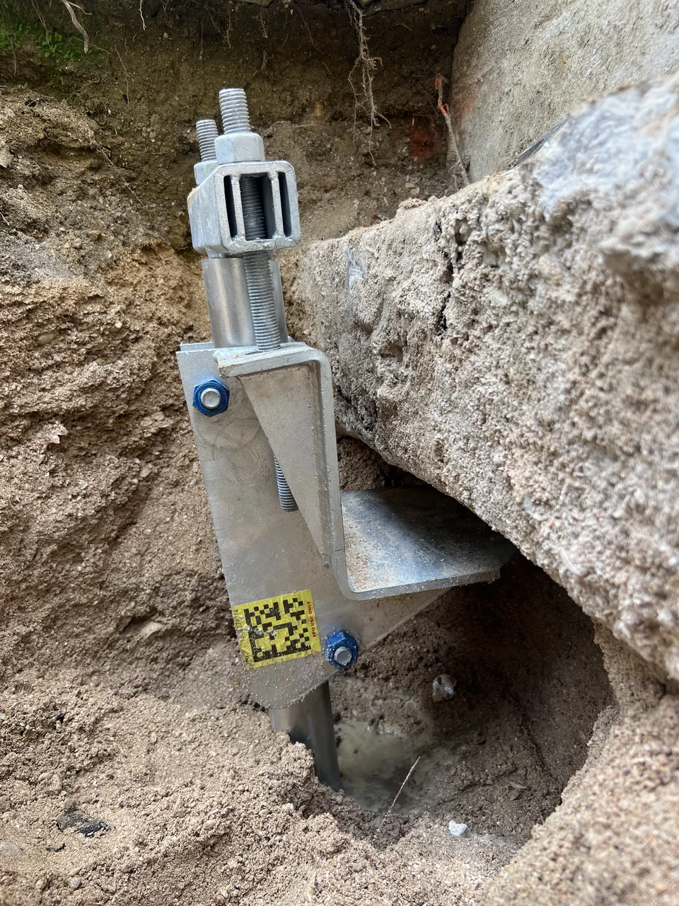
The bracket is part of the structural load path
The load path runs from the existing footing into the bracket, through the pile shaft and connections, and into the ground through the bearing system. Each component and connection matters. A pile rating alone does not establish the capacity of the repaired foundation.
The engineer and system documentation address the existing concrete, bracket bearing and attachment, load eccentricity, supported shaft length and compatibility of the components. A compression underpinning bracket must not be assumed to provide an uplift connection. Identify the required action and the rated arrangement rather than treating all brackets as interchangeable.
Assessment before opening the footing
- Available structural and foundation drawings, including footing dimensions.
- Condition of the concrete and reinforcement where load will be transferred.
- Level survey and a record of existing cracks or movement.
- Ground investigation, groundwater and the suspected mechanism of distress.
- Utilities, access, adjacent structures and temporary support requirements.
- Installation, load-transfer and monitoring sequence, with defined acceptance criteria.
Older foundations may not match the available drawings. The work plan should identify how unexpected footing dimensions or poor concrete will be reviewed.
A coordinated execution sequence
- Establish the baseline. Record levels and relevant existing conditions before work starts.
- Expose the specified area. Follow the staged excavation and support plan so the investigation or installation does not undermine the structure.
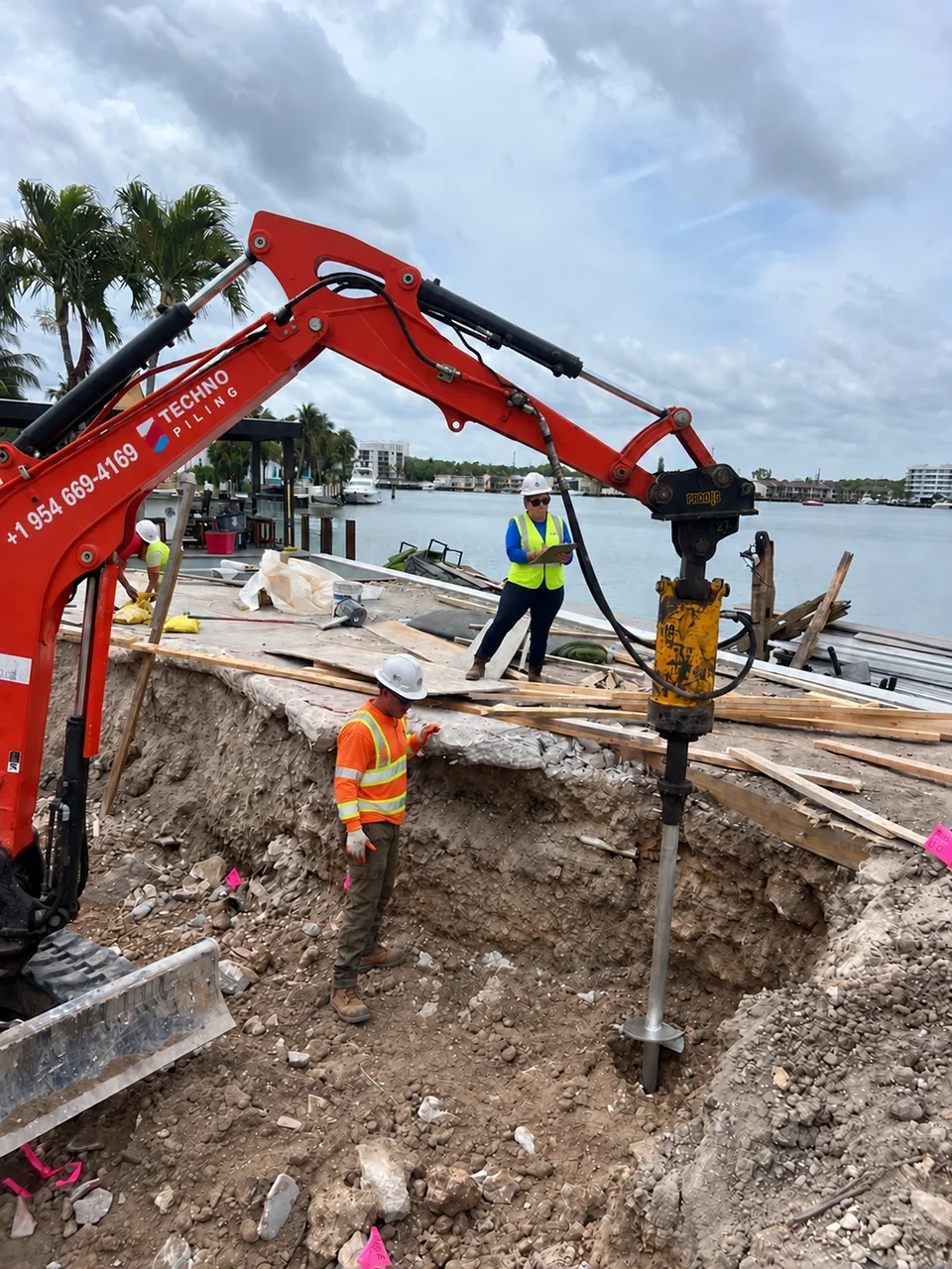
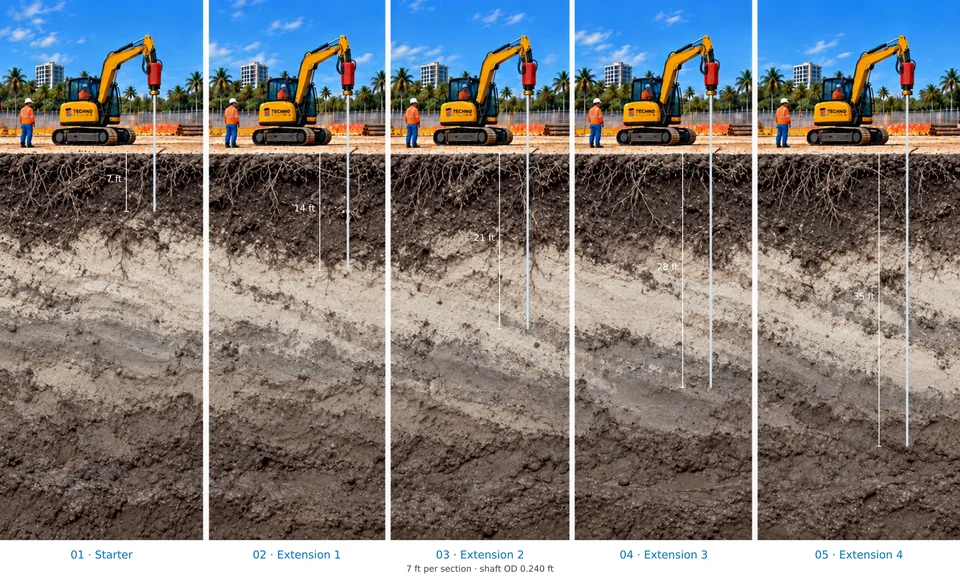
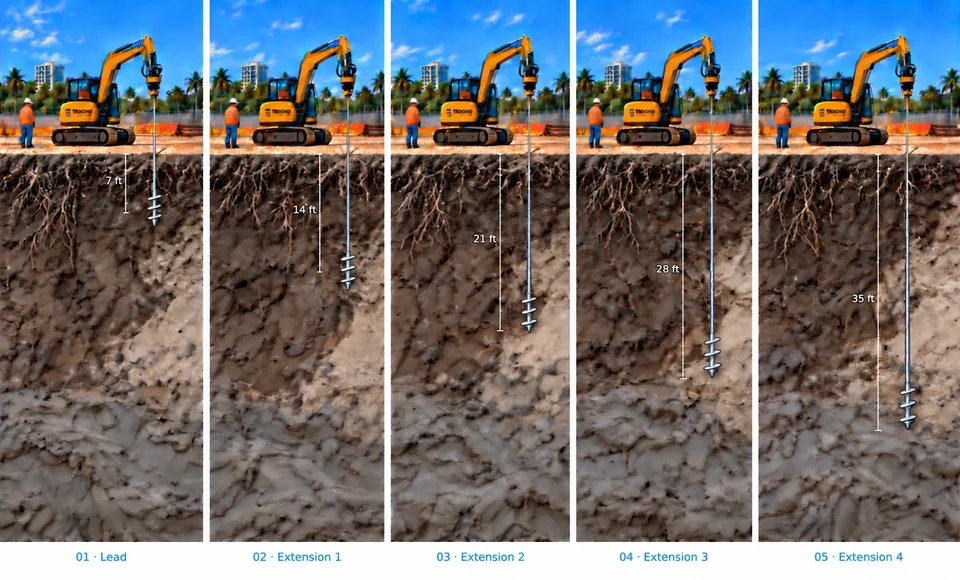
- Install the pile. Record location, alignment, components, depth, torque and installation observations.
- Fit the approved bracket. Prepare and complete the connection in accordance with the engineered detail and component requirements.
- Transfer load in a controlled sequence. Apply specified preload or lifting operations while observing the structure and instrumentation.
- Complete the permanent condition. Secure the connection, complete inspections and tests, reinstate the work area and document the final levels.
Stabilizing a foundation is not a promise to re-level it
A controlled load-transfer operation may be specified without lifting the building. Where lifting is proposed, the engineer establishes the sequence, limits and monitoring requirements. The structure, finishes, utilities and neighboring support points must be considered together.
It is not appropriate to promise that every crack will close or that a building can be restored to a chosen level solely because piles have been installed. Unexpected structural response requires review of the operation rather than continued movement to reach a marketing target.
Verification and closeout
Records should identify each pile and bracket, component details, installation data, the connection inspection, any required tests, load-transfer observations and before-and-after levels. Record deviations and the agreed resolution. Where post-installation monitoring is part of the plan, define the reference points, timing and reporting responsibilities.
Supporting the structure does not automatically resolve every contributing site condition. Drainage, leaks, surrounding fill or adjacent work identified in the assessment may require a coordinated response.
Requesting an underpinning review
Provide the address, photographs, available drawings, ground information, access details and any survey or engineer assessment. Explain whether the requested scope is stabilization, additional support for altered loads or evaluation of a movement-correction plan. This helps separate the installation scope from the diagnosis and design work.
General technical guidance. Project drawings, geotechnical recommendations and approved system details govern the work.